System
Detail Diagram
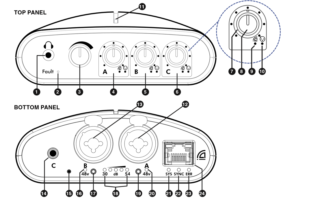
1 | 1/8" Stereo Headphone Output | 13 | Input "B" Balanced XLR or 1/4" Input |
2 | Headphone Fault LED | 14 | Input "C" Unbalanced 1/8" Stereo Line Input |
3 | Master Volume | 15 | Reset Switch |
4 | "A" Input | 16 | Input "B" Phantom Power Indicator |
5 | "B" Input | 17 | Input "B" Gain & Phantom Power Button |
6 | "C" Input | 18 | Gain Indicator LEDs for Input "A" or "B" |
7 | Dante Input Level (Knob Ring) | 19 | Input "A" Gain & Phantom Power Button |
8 | Analog Input Level (Knob Tip) | 20 | Input "A" Phantom Power Indicator |
9 | Dante Signal & Clip Status LED | 21 | "SYS" Dante Status Indicator |
10 | Analog Input Signal & Clip Status LED | 22 | "SYNC" Dante Communication Indicator |
11 | User-changeable Multi-color LED (for identifying multiple M8RXs) | 23 | "ERR" Error Indicator |
12 | Input "A" Balanced XLR or 1/4" Input | 24 | Dante & PoE+ Power RJ45 for 100 BaseT Ethernet Connector (only use unshielded cables) |
Standouts
- Two ultra-low noise studio-quality discrete microphone preamplifiers
- Locally adjustable microphone gain, in selectable increments between 30 and 54 dB
- Local volume control of up to 8 channels of audio (4 local analog inputs and 4 Dante digital inputs)
- 1/8" Stereo Input (input 3/4)
- Ultra-low distortion of 0.001% THD+N (even with 60 dB of gain on the microphone preamp!)
- PoE+ power guarantees ground isolation between M8RX interfaces
- Standard unshielded CAT6 cabling delivers power and Dante digital audio to each M8RX
- Zero latency headphone monitoring of the local analog inputs
- All 4 local analog input channels are made available on the Dante network as sources
- Can use stand-alone (without a Dante network connection) as a small microphone preamp, analog mixer, and headphone amplifier (great as a more-me system)
- Easily mounts to a mic stand using the built-in ¼"-20 camera-tripod mount and the included 5/8"-27 adapter
M8RX Construction
The Switch Back M8RX is constructed of UV-stabilized ABS and has a built-in standard camera tripod stand mount (1/4" 20 thread). Additionally, a tripod thread to microphone stand adapter (1/4"-20 to 5/8"-27) is also included to allow mounting on a microphone stand.
Status Indicators
The M8RX has six types of status indicators:
Front Color-Changing LED
A large color changing indicator is provided to allow easy identification when multiple Switch Back M8RX interfaces are used in a setup. The color of this indicator is user-selectable by pressing both input buttons simultaneously for several seconds. This indicator will also automatically cycle through the color spectrum when booting and also when the identify function is triggered in the Dante Controller software.
Dante
The Dante bus has three indicators that are bi-color. They are BLUE under normal operating conditions and RED alerting the user a problem exists. The SYS indicator is BLUE if at least one other Dante device is connected to the same network, otherwise it is RED. The SYNC indicator is BLUE if the internal clock circuitry is operating properly, otherwise it is RED. The ERR indicator is normally off. If there is a problem with the firmware or memory then the ERR indicator will turn RED.
Gain
Five GREEN indicator LEDs located below and between the XLR input connectors will illuminate when one of the input buttons is pushed (located below each XLR input). These indicators display the current input sensitivity for each input from -54dBu to -30dBu for XLR microphone inputs (-36dBu to -12dBu for ¼" inputs). These indicators will automatically turn off after a few seconds of pressing one of the input buttons.
Phantom Power
A single ORANGE LED indicator is located below each XLR input with the label "48v" below it. When illuminated, 48 volts DC is present on XLR pins 2 and 3 with respect to pin 1. This provides power to any microphones requiring phantom power. This is toggled on or off by holding one of the input buttons for 2 seconds.
Audio Signal
Six indicator LEDs located below the input volume controls illuminate BLUE when signal is present and RED when the input is too strong and causing distortion. 3 of these indicators represent the A, B, and C Dante inputs (red Dante logo above each) and 3 of these represent the A, B, and C analog inputs (blue XLR logo above each).
Headphone Amplifier Fault
The fault indicator is normally off and only illuminates RED if an over-current or short circuit condition occurs for a long enough period to cause overheating of the amplifier (100°C or 212°F). Continued use of the amplifier in a fault condition is not recommended as it can degrade the amplifier's performance and life.
Controls
The M8RX has four different types of controls:
Input Volume Knob
There are 3 input volume knobs labeled "A", "B", and "C". Each of these knobs has two parts that can be adjusted independently: a tip and a ring. The tip of each volume knob adjusts the level of each analog input located on the bottom of the M8RX. The ring of each volume knob adjusts the level of each Dante input which arrives over the Ethernet network connection. These can be assigned from any other Dante device on the network using the Dante Controller software. These volume knobs only adjust the audio level to the headphones, they do not affect the audio level sent to the Dante network.
Master Volume Knob
The master volume is used to set the overall volume level of the headphone output.
Input Gain Push Button
Each button is located below its respectful channel's XLR inputs on the bottom of the M8RX. Pushing one of these buttons will display the current input gain for the chosen input on the 5 GREEN LED indicators below and between the two XLR inputs. Every press of this button after the initial press will step the gain up or down one step. The gain first steps up until it gets to the top, and then it steps back down until it gets to the bottom and continues to repeat this pattern. Gain has input sensitivity adjustments from -54dBu to -30dBu for XLR microphone inputs (-36dBu to -12dBu for ¼" inputs). Holding one of these push buttons for 2 seconds will toggle the phantom power for the input which is indicated by an ORANGE LED below the XLR input. Pushing and holding both of these buttons at the same time will cycle through colors on the font color-changing LED. These buttons can also be locked or unlocked.
Dante Failsafe Button
Accessible through a small hole using a paper clip or small screw driver. Only use this button if instructed by our technical support.
Inputs
The M8RX has three different types of inputs:
Balanced Mono Input
The M8RX has two balanced mono inputs labeled "A" and "B". These inputs have a special "combo" connector that allows either a XLR microphone connector or a ¼" TRS connector. The XLR input is designed for microphones and has adjustable input gain with sensitivity adjustments from -54dBu to -30dBu and a 48 volt phantom power supply that is selectable per input. The ¼" input has an 18 dB pad and is designed for line-level and instrument inputs with input sensitivity adjustments from -36dBu to -12dBu. These two inputs can be monitored locally in the analog domain (zero latency) by turning up the tips of volume knobs "A" and "B" respectively. These inputs are also available on the Dante network as channels 1 and 2.
Unbalanced Stereo Input
The M8RX has one unbalanced stereo input on a 1/8" TRS connector labeled "C". This input is designed for line-level sources and has a fixed input gain sensitivity of -10dBu. This input can be monitored locally in the analog domain (zero latency) by turning up the tip of volume knob "C". This input is also available on the Dante network as channels 3 (left) and 4 (right).
Dante Digital Input
The M8RX has 3 channels of digital audio inputs from the Dante network. These can be monitored using the rings on volume knobs "A", "B", and "C". The first two inputs are mono and audio can be routed to them using the Dante Controller software on channels 1 and 2 of the M8RX. Dante input "C" is a stereo input and audio can be routed to it using the Dante Controller software on channels 3 (left) and 4 (right).
If Dante sampling rates 88.2kHz or 96kHz are used, only 2 channels of audio are supported: "A" and "B".
Lock Out Gain/Phantom Power Buttons
Procedure to lock out Gain/Phantom Power Buttons:
- Unplug power.
- Press and hold BOTH blue push buttons (A and B) while inserting network cable to reapply power.
- Once power is reapplied, release BOTH push buttons.
- Press either blue button to lock or unlock the Gain/Phantom Power. The LED on the front of the M8RX will glow RED when LOCKED and GREEN when UNLOCKED.
- Once set, it will take approximately 10 seconds for the M8RX to reboot (cycles through the color scheme).
- To change settings again, repeat the steps above.
Headphone Amplifier
When using multiple headsets, the total impedance should not go below 16 ohms. Optimum headphone amplifier performance is achieved with a load of 32 to 50 ohms. At 50 ohms, the amplifier is capable of sustaining 2 watts of power! The headphone amplifiers are very powerful and can easily damage in-ear transducers, headphones, and your hearing; exercise great care in adjusting the master volume. The amplifiers are short circuit protected and have a fault indicator.