OCTO Mixer
Mixer Detail Diagram
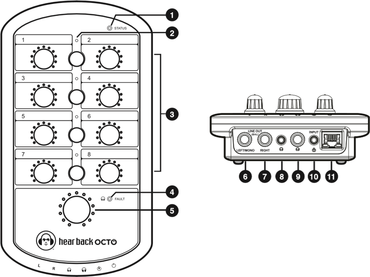
1 | Bi-Color Bus Status Indicator | 7 | Right Line Output |
2 | Link Indicators (Channels 1/2, 3/4, 5/6, 7/8) | 8 | 1/8" TRS Headphone Output |
3 | Mono Channels 1-8 / Stereo Link Master Level (1, 3, 5, 7) | 9 | 1/4" TRS Headphone Output |
4 | Headphone Amplifier Fault Indicator | 10 | Stereo Auxiliary Input |
5 | Master Volume | 11 | RJ45 Connection |
6 | Left/Mono Line Output |
Mixer Features
- Local control of up to ten channels of audio
- Master volume
- 24-bit D/A converters
- Less than 1.5 millisecond total system delay
- Bus status indicator
- Headphone amplifier fault indicator
- Link indicators/capacitive touch buttons
- Standard CAT5e/6 power and signal connection
- Balanced, mono/stereo, line outputs
- +4 dBu level TRS unbalanced stereo AUX in:
- Expand numbers of mixes
- Drum module/metronome or local mix input mono
Mixer Construction
The Hear Back OCTO Mixer is constructed of UV-stabilized ABS and has a built-in mic stand mount. Cable strain relief greatly reduce stress on the CAT6 cable connectors and the Mixer RJ45 connector.
Status Indicators
The Mixer has three types of status indicators:
1. Bus
The bus indicator is a bi-color LED that is BLUE under normal operating conditions, indicating the HearBus clock is present. In the absence of the clock, the indicator turns RED alerting the user a problem exists at the Hub or connection to the Hub. The indicator will alternate RED and BLUE during a headphone fault.
2. Link
The link indicators illuminate BLUE whenever the associated link capacitive button(s) are pressed for one second, verifying the link. Button settings are stored in non volatile flash memory whenever power is removed.
3. Headphone Amplifier Fault
The fault indicator is normally off and only illuminates red if an over-current or short circuit condition occurs. The circuit shuts down the headphone amplifier and upon cooling returns to normal operation. Continued cycling of the fault circuit is not recommended as excessive cycling can degrade the amplifier's performance and life.
Link Operation
Inputs are typically mono and are controlled using the mono control knobs 1-8. The mono signals are center-panned in the stereo field when the link indicator is off.
When a pair of mono inputs are linked, three things occur:
- The left channel becomes the link master volume control for the stereo pair.
- The two inputs are hard panned left and right. Stereo signals are realized by using a pair of the mono inputs: 1/2, 3/4, 5/6 and/or 7/8, by pressing the capacitive link button between the pair of mono inputs for one second.
- The right mono volume now becomes inactive.
Line Outputs
Left/Mono and Right/Stereo 1/4 inch Tip, Ring, and Sleeve line
outputs are provided. When the Left/Mono jack only
is used, left and right are summed as a mono output. The
line outputs may be used simultaneously with the headphone
outputs and are both controlled with the master volume knob.
In the event of ground loops when connecting the Mixer line
outputs to other devices that have an earth ground, it may
become necessary to lift the shield at the Mixer outputs.
NEVER lift or disconnect the AC safety ground of any device.
Aux In
The auxiliary input is a 1/8 inch Tip, Ring, and Sleeve input optimized for +4 dBu input levels. These signals are summed into the analog section of the Mixer just upstream of the master volume. The input permits another stereo mix to be inserted into the audio stream. Examples of use would be a drum machine click track into the drummer's Mixer. Another application would be a stereo mix from a guitar or keyboard local mix, another Hear Back OCTO Mixer, creating a total of ten channels controlled from your Mixer.
Master Volume
The master volume is used to set the volume of the headphones and the line outputs. When using the line outputs in conjunction with the headphones, optimize the mix for the headphones and then adjust the device connected to the line outputs to balance the gain. Follow the same procedure if using the AUX input; once the desired mix is obtained, adjust the source to get the desired level at the AUX input.
Headphone Amplifier
The headphone amplifier outputs are paralleled outputs. When using multiple headsets, the total impedance should not go below 16 ohms. Optimum headphone amplifier performance is achieved with a load of 32 to 50 ohms. At 50 ohms, the amplifier is capable of sustaining 2 watts of power! The headphone amplifiers are very powerful and can easily damage in-ear transducers, headphones, and your hearing; exercise great care in adjusting the master volume. The amplifiers are short circuit protected and have a fault indicator.