PRO Hub
Detail Diagram
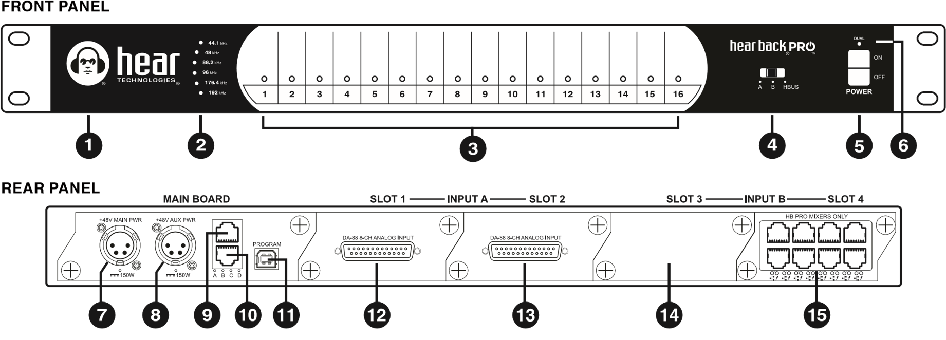
1 | LED Status Indicator | 9 | HBUS Input |
2 | Sample Rate LED Indicators | 10 | HBUS Output |
3 | Audio Input Channels 1-16 Level LED Metering | 11 | USB Connection |
4 | Input Selector Switch | 12 | Card Slot 1 (8-channel Analog Input shown) |
5 | Power Switch | 13 | Card Slot 2 (8-channel Analog Input shown) |
6 | "Dual" Power LED Indicator | 14 | Card Slot 3 (shown unpopulated) |
7 | Main 48V Power Input | 15 | Card Slot 4 (8-port Network Card shown) |
8 | Secondary 48V Power Input |
Features
- Three switch selectable 16-channel input sources:
- Input A (Slots 1 & 2)†
- Input B (Slots 3 & 4)†
- HBUS
- 24-bit Delta-Sigma A/D converters (Analog Cards)
- Six user-selectable sample rates, indicated by LEDs: 44.1 kHz, 48 kHz, 88.2 kHz, 96 kHz, 176.4 kHz, and 192 kHz
- Less than .25 milliseconds total system delay (latency) at 192 kHz
- 16 RGB LEDs intuitively display signal / peak levels for channel metering†
- Standard CAT6 delivers power and signals to Mixers
- Daisy-chain via HBUS for very large systems
- Quiet, temperature-controlled fan (only runs when internal temperature reaches 43° C or 110° F)
- 1 RU chassis
- Modular I/O card-slot configurable mainframe
- Gigabit Ethernet network fabric, with enough bandwidth to support up to 96 channels of audio at 192/176.4 kHz, 128 channels at 96/88.2 kHz or 48/44.1 kHz
- 48 volt Power Over Ethernet supply
- Port for redundant power supply (or to power more than 16 Mixers)
- USB port only for upgrading from older firmware versions
- Error indicating logo glows "RED" should a fault arise
†Both A and B inputs are used simultaneously. Switching between A and B selects clock source and channel 1. Metering of the 16 channels selected as the clock source will be displayed via the 16 RGB LEDs on the front panel.
Channels
If you are using from 1 to 32 channels you will only need one Hear Back PRO Hub. If you are using 33 channels or greater you will need multiple Hubs.
Channel Names and Links
Channels names can be assigned via the PRO Connect software. Instructions can be found here: Digital Overlay
Channels can also be stereo linked via the PRO Connect software. More information on the benefits of linking can be found in the PRO Mixer section.
Channel names and links are both stored in the Hub's onboard memory.
Channel Locations
Hub 1: Channels 1-32
Hub 2: Channels 33-64
Hub 3: Channels 65-96
Hub 4: Channels 97-128
Example
An engineer needs to send out up to 64 channels of analog audio to the personal monitoring system. They would need the following hardware:
2 x Hear Back PRO Hubs (Additional PRO Hubs or PRO Mixer Distros to connect the PRO Mixers)
8 x Hear Back PRO Analog Input Cards (4 in each Hub)
Each Hear Back PRO Analog Input Card supports 8 channels of audio. Each Hub will then support up to 32 channels (4 x 8 = 32) giving the engineer a total of 64 channels.
HBUS
The HBUS permits daisy-chaining of multiple Hubs up to 500 feet apart using the HBUS input and HBUS output. This HBUS is great for inter-studio or stage-to-stage connections, as well as daisy chaining for very large systems.
HBUS RJ45 pin-outs are the same as standard gigabit Ethernet RJ45 pin-outs, only without power. The pin-outs are wired as shown below:
| Pin | Pair | Description | Suggested Termination Color Scheme (568B)**** |
|---|---|---|---|
| 1 | A+ | Bidirectional Data Pair A | White/Orange |
| 2 | A- | Bidirectional Data Pair A | Orange |
| 3 | B+ | Bidirectional Data Pair B | White/Green |
| 4 | C+ | Bidirectional Data Pair C | Blue |
| 5 | C- | Bidirectional Data Pair C | White/Blue |
| 6 | B- | Bidirectional Data Pair B | Green |
| 7 | D+ | Bidirectional Data Pair D | White/Brown |
| 8 | D- | Bidirectional Data Pair D | Brown |
****Color Scheme 568A is also acceptable, but do not crossover from 568A to 568B.
Multiple Hubs
All Hubs need to set to the same sampling rate. If there's a mix of input cards (analog and digital), the digital card must be the CLOCK MASTER and then the analog will SLAVE to it. If there are multiple digital cards, the digital audio must all come from the same source and be word-clock synchronized or there will be pops and clicks in the audio. You cannot mix 16-channel and 32-channel cards. In a multi-Hub system with both digital and analog cards, Hub 1 must have a digital card selected as a source to use the digital clock. Otherwise, audio pops and clicks will occur.
Connecting Multiple Hubs
Use only unshielded CAT5e or CAT6 Ethernet cables.
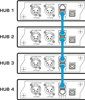
- Connect Hub 1 HBUS OUT to Hub 2 HBUS IN
- Connect Hub 2 HBUS OUT to Hub 3 HBUS IN
- Connect Hub 3 HBUS OUT to Hub 4 HBUS IN
Hub Position Indicator
A Hub's position (Hub number) can be seen when powering ON or by switching from A or B to HBUS then back to A or B. The LEDs on the Hub's front panel will light either WHITE or BLUE.
The WHITE LED indicates the Hub's position in the Hub chain (i.e. if LED 2 is WHITE, then that Hub is Hub 2 in that Hub chain).
Input Selector Switch
The input selector switch gives the user a simple way to select any one of the three input/clock sources without a patch bay, router, or rewiring.
The Input Selector switch is located on the front panel of the Hear Back PRO Hub. This switch has different functions depending on the FW version installed.
For FW V2, switching between A and B selects 16 channels from either A or B.
For FW V5 and 16-channel card versions of V6 and later, inputs A and B are used simultaneously. Selecting between A and B selects the Clock Source and sets the 16 channel RGB LEDs to display that source. See the following chart.
| INPUT SELECTOR SWITCH POSITION | CARD SLOT | RESULTING OUTPUT CARD CHANNELS |
|---|---|---|
| A | 1 | 1 THRU 16 |
| 3 | 17 THRU 32 | |
| B | 3 | 1 THRU 16 |
| 1 | 17 THRU 32 |
For 32-channel card versions of V6 and later firmwares, all 32 channels are received from the selected card either A or B. The switch also determines the Clock Source.
Input Metering
The Hub features a unique input metering circuit consisting of one RGB LED for each of the first 16 input channels. Each LED provides four visual levels that correspond color to signal strength in dBu:
| Analog Input Cards** | |
|---|---|
| Signal Strength | Color |
| -29 dBu to -18 dBu RMS | Blue |
| -18 dBu to 0 dBu RMS | Green |
| 0 dBu to +17.5 dBu RMS | Yellow |
| +17.5 dBu (clip) Peak | Red |
**Analog Input Cards with jumpers removed.
| Digital Input Cards | |
|---|---|
| Signal Strength | Color |
| -46 dBFS to -35 dBFS RMS | Blue |
| -35 dBFS to -17 dBFS RMS | Green |
| -17 dBFS to -0.5 dBFS RMS | Yellow |
| -0.5 dBFS Peak | Red |
Status Indicating Hub Logo
The illuminated logo serves as an indicator for several purposes. Under normal conditions, the logo will be BLUE, indicating valid clock is present (could be internal or external). A RED logo indicates no valid clock is present. If the logo is blinking RED, this typically indicates a temperature problem, but could indicate something else. Refer to troubleshooting section for detailed information.
Internal Fan
The internal temperature-controlled fan operates whenever the internal temperature reaches 43° C or 110° F. In studio or indoor use, the fan should rarely come on. The Hub should be rack mounted away from high temperature devices such as power amplifiers. Please ensure our recommended clearances listed at the beginning of this manual are met.
High temperatures will cause problems!
Dual Power Ports
The Hub supports two external power supplies. The second power supply serves two purposes: to provide redundancy in case of power failure, and to power more than two network cards (greater than 16 Mixers) in a single Hub. On the front of the Hub, an LED directly above the power switch will be lit if two power supplies are present. This provides an easy way to know if one of the power supplies has failed. On the back of the Hub, an LED is present directly under each power port, and will be lit if power is present at that port.
Firmware Version
It is recommended to check and update the firmware version of all PRO equipment using the PRO Connect Software.
New interface. New level of control.
PRO Connect provides a web-based interface to update, configure, and control your Hear Back PRO and Switch Back PLUS systems.
 [Download for Windows]
 [Download for macOS]
To check the version on the Hub directly:
- Apply Power.
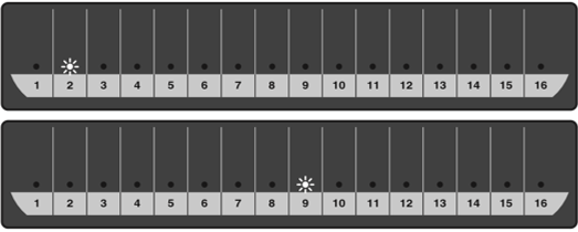
- Immediately after all the LEDs turn "on", slide the "Input Selector Switch" through all "A,B, HBUS" options, then return to the original selection (Figure 1).
- Channel LEDs will flash WHITE to indicate firmware version - once for major number, then once for minor number (e.g. LED #2, then LED #9 = V2.9) (Figure 2).

IO Cards
The modular Hub consists of four card slots, which can be populated with any configuration of input and/or output cards to fit your needs.
Installing an IO Card
Make sure you touch a metal object to discharge any static before proceeding with installation.
- With power disconnected, orient the Hub with the back towards you.
- Select the blank slot you wish to utilize and remove the plate and two Phillips screws.
- Slide the card into the slot, and push gently as the gold fingers mate with the front panel connector. You should feel it "snap" into place.
- Tighten the set screws on the front of the card.