PRO Mixer
Mixer Detail Diagram
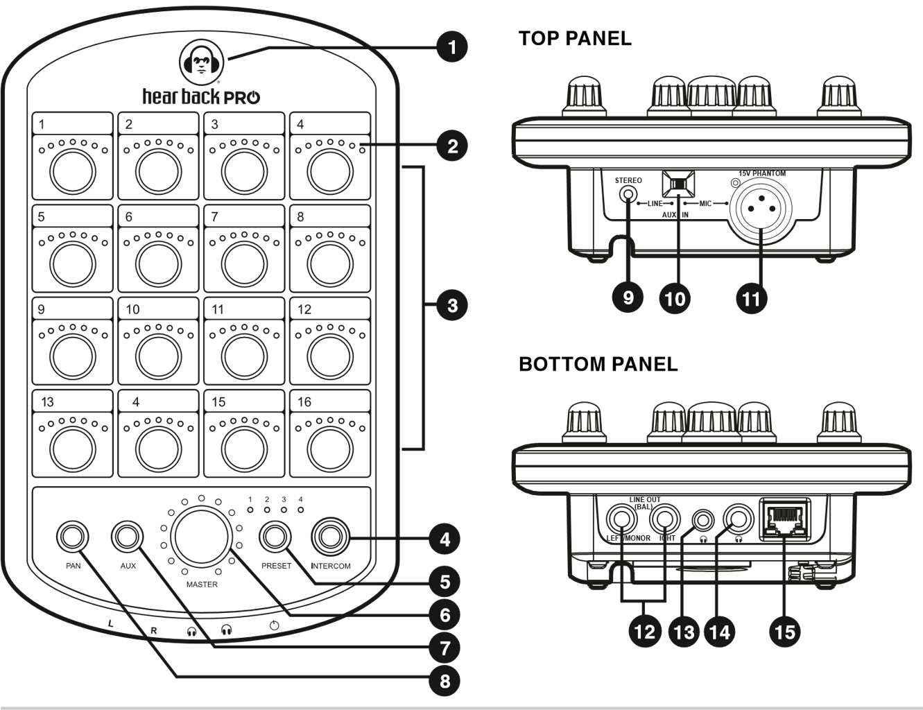
1 | LED Status Indicator | 9 | Auxiliary 1/8" Stereo Unbalanced Audio Input |
2 | LED Level Indicators | 10 | Auxiliary Input Switch |
3 | Volume/Pan Control Knob for Each Audio Channel | 11 | Auxiliary Balanced XLR Microphone Input with 15V Phantom Power |
4 | "Intercom" Button | 12 | 1/4" Left/Mono and Right Outputs (Balanced) |
5 | "Preset" Button | 13 | 1/8" TRS Headphone Output |
6 | "Master" Control Knob (Volume / Aux) | 14 | 1/4" TRS Headphone Output |
7 | "Aux" Input Button | 15 | Gigabit Ethernet (GbE) Connection with PoE+ (Power over Ethernet) |
8 | "Pan" Button |
Mixer Features
- Local control of all available audio channels
- Receive power and audio over one Ethernet cable, up to 500' from Hub to each Mixer
- Side-mounted card slot for future expansion
- Large master knob controls overall main mix, AUX, and intercom levels independently
- 24-bit D/A and A/D delta-sigma converters
- Error indicating logo glows "red" to indicate a problem, and flashes "red" when headphone amplifier temperature reaches 100° C (212° F)
- Volume / panning / stereo link control of all channels of audio
- Balanced mono/stereo, line level outputs
- Store up to 4 recallable presets, while most recent configuration is remembered after power-down
- Intercom feature allows communication to anyone with a Hear Back PRO Mixer or Virtual Mixer Card
- Selectable 1/8 inch TRS stereo unbalanced and XLR mono balanced (with 15V phantom power) AUX inputs:
- Microphone input for crowd/ambiance mic, or for use with intercom
- Drum module/metronome or local mix input
- One 1/8 inch TRS headphone output
- One 1/4 inch TRS headphone output
Mixer Construction
The Hear Back PRO is constructed of UV-stabilized ABS and has a built-in mic stand mount. The cable strain relief channel (molded into the Mixer) greatly reduces stress on the CAT6 cable connectors and the Mixer RJ45 connector.
Status Indicating Mixer Logo
The illuminated logo serves as an indicator for several purposes. Under normal conditions, the logo will be BLUE, indicating digital audio packets are being received. A PURPLE logo indicates audio packets are being dropped, and a RED logo indicates no valid packets are being received. If the logo is blinking RED, this indicates the headphone amplifier has overheated. Check the troubleshooting section if any color other than a BLUE logo occurs.
Volume
Each channel knob controls the volume of its respective channel(s) within the mix. The master knob, by default, controls the volume of the overall mix. Volume operation is indicated by BLUE LEDs. Volume scales from 0% to 100%, left to right, respectively.
Master Volume
The master volume is used to set the volume of the headphones and the line outputs. When using the line outputs in conjunction with the headphones, optimize the mix for the headphones and then adjust the device connected to the line outputs to balance the gain.
Pan Operation
To control panning of channels, press the PAN button. The PAN button and channel knob LEDs will turn GREEN to indicate that the channel knobs now control panning position of the audio within the stereo field. To return to volume control, press the PAN button again, or wait 30 seconds from the last adjustment for the system to automatically return to volume control.
With FW V5 and later, pressing PAN while in volume mode will show PAN (GREEN LEDs) and pressing again will show AQUA width controls for channels that are stereo.
Stereo Link Operation
Each audio channel comes from a mono source, and is therefore center-panned by default for any firmware version.
To quickly hard-pan two channels left and right to create a stereo pair via a PRO Mixer:
- Press and hold PAN for two seconds to enter linking mode.
- Channel LEDs will flash GREEN. Twist one of two adjacent channel knobs (1-2, 3-4, 5-6, etc.) to link them. Channel level indicators will illuminate LEDs #1, #2, #3, #4 above the first knob and LEDs #4, #5, #6, #7 above the second knob.
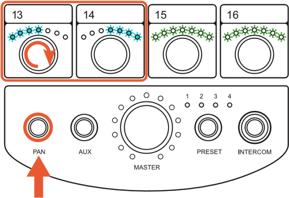
- To unlink channels, hold the PAN button until the LEDs flash GREEN, then twist one of the linked knobs until only LED position 4 is lit.
- To EXIT, press PAN button or wait 30 seconds to go back to default volume levels.
This operation can only be performed on adjacent pairs of channels. Therefore, channel 1 can only be linked with channel 2, channel 3 with channel 4, and so on. Upon linking channels, the volume of the right channel is set according to the volume of the left channel. Volume adjustments to either stereo-linked channel now effects both channels in unison.
For FW V2, the link settings are stored on each individual Mixer. For example, Mixer #1 may have channels 1 and 2 linked, Mixer #2 may have them set as mono.
For FW V5 and later, link settings are stored in the Hub. For example, if channels 1 and 2 are linked, this is global over all Mixers. Stereo placement and width are added. These links can also be set globally via the PRO Connect software.
Aux Input Operation
The auxiliary input connections provided are one 1/8 inch TRS stereo unbalanced input optimized for 0 dBu input level and one XLR mono balanced input optimized for -42 dBu input level, selectable via the switch located adjacent to the connections. The inputs provide another mono or stereo-mixed channel to be inserted into the Mixer. Examples of use would be a drum machine click track into the drummer's Mixer, or a crowd/ambient mic in everyone's Mixer (which can double as the intercom mic). Another application would be a stereo mix from a guitar, keyboard, or a mix from another Hear Back or Hear Back PRO Mixer, providing additional input sources controlled from your Mixer.
- Press the AUX button to change the function of the master knob to control the volume of the auxiliary input in the mix.
- AUX button and master knob LEDs will turn RED to indicate this function is active.
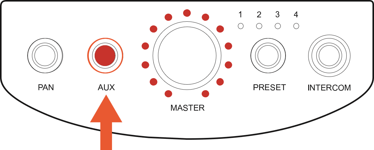
- Press the AUX button again to exit auxiliary volume control, or wait 30 seconds from the last adjustment for the system to automatically return the master knob to its default function.
Preset Operation
The Hear Back PRO Mixer has the ability to store up to four system states in internal memory for easy session settings recall. Pressing the PRESET button will step through presets 1 – 4, one at a time.
Save a Preset
-
Press and hold PRESET for two seconds. The current preset LED will begin flashing quickly.
-
Keep holding if you wish to save to a different location (unit will scan across the four preset locations). When the desired preset numer is reached, let go of the PRESET button.
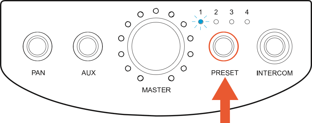
For FW V2, upon making any control change while using a preset, the preset number will slowly blink to let you know your new settings have not been saved. To save the changes to the preset, simply hold the PRESET button for 2 seconds until the preset number rapidly blinks, then release.
For V5 and later, presets are saved automatically when powering down or pushing the PRESET button to recall another preset.
Preset Copy and Paste
Presets can be sent to another PRO Mixer with the following procedure:
- Press and hold PRESET (one of the Preset LEDs will flash), then while holding PRESET press the INTERCOM button.
- All four of the preset LEDs will flash quickly indicating that the Mixer is in "copy" mode.
- Release buttons.
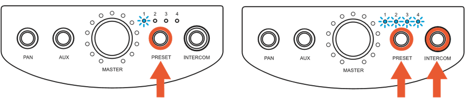
- To "paste" the settings from this Mixer to another Mixer:
- Go to the Mixer that you wish to paste the settings to and press PRESET and INTERCOM at the same time.
- All the LEDs will flash indicating that the settings were copied. You must save these settings to a preset location if you wish to retain the copied settings.
-
note
This does not copy all the presets, ONLY the current audio levels and pan settings for FW V2 plus routing and submixing for FW V5 and later.
- The Mixer you're copying from will continue to stay in "copy" mode for up to 5 minutes, allowing you to "paste" the settings to other Mixers.
- To EXIT the "copy" mode, press PRESET button, or wait for the timeout.
Intercom Operation
The intercom function transmits the AUX IN source to everyone with a Hear Back PRO Mixer on the same network. By default, the input gain for the intercom source is set to 75%. When receiving audio from another Mixer, the intercom has an auto gain feature that automatically adjusts the incoming signal so that you'll always hear it over your mix.
To broadcast your intercom momentarily, simply press and hold the INTERCOM button. The button and the master knob LEDs will light up RED to indicate that the intercom is broadcasting, and that the master knob now controls the input gain for your intercom source.
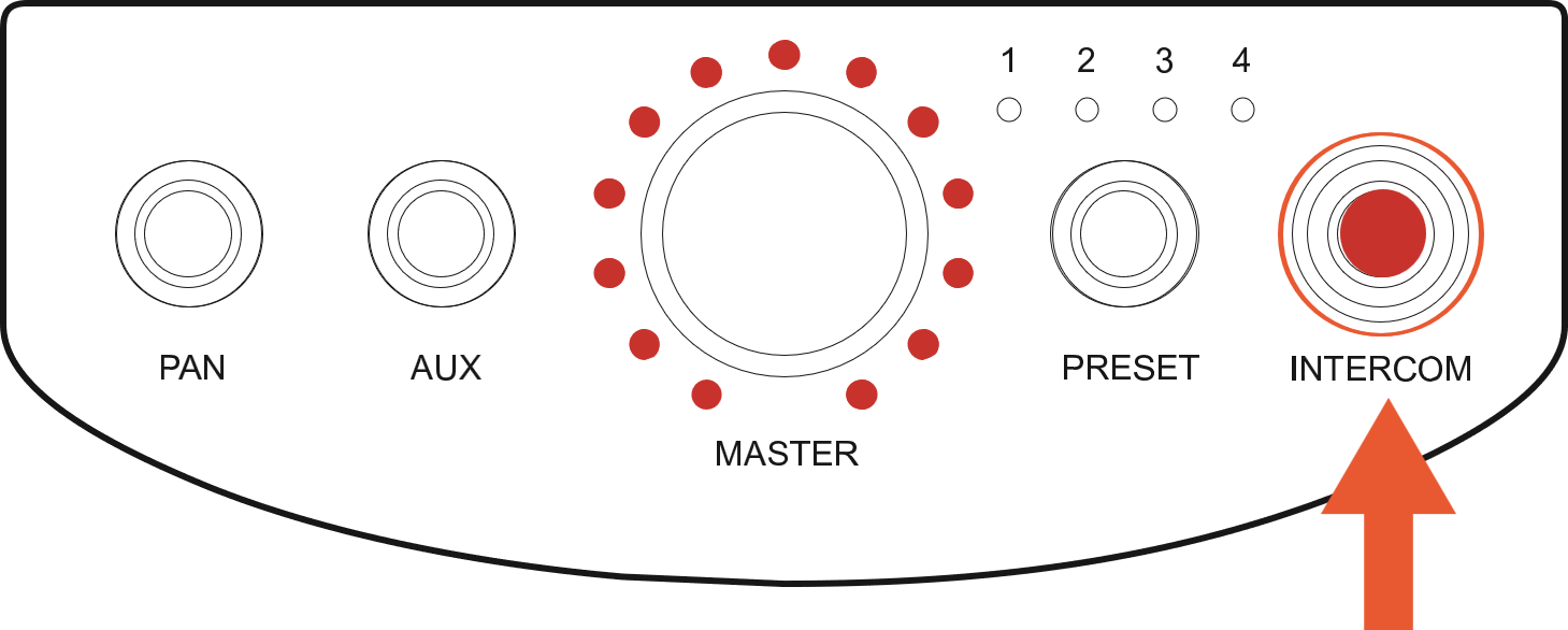
The Mixer's intercom can be latched for continuous broadcast. For FW V1 and earlier V2 releases, rapidly push the INTERCOM button three times in succession. For V5 and later simply touching the button quickly will latch it. The button and the master knob LEDs will stay RED to indicate that the intercom is broadcasting. Press the INTERCOM button once more to stop continuous broadcast and return the master knob to its original function.
The INTERCOM button will rapidly blink RED to indicate that a broadcast from another Hear Back PRO is currently being received.
FW V2 allows only one Mixer to broadcast at a time. FW V3.6 and later allow up to (4) people to talk simultaneously and all other Mixers can still listen in. Those other Mixers, on the same network, are "locked out" from broadcasting until a transmitting Mixer's INTERCOM button is released or unlatched. With FW V5 and later, four Mixers can be latched at the same time to carry on a conversation.
Enable/Disable Intercom
The easiest way to enable or disable intercom is to use the PRO Connect app.
To enable / disable the INTERCOM button FW V6 or earlier or to enable / disable incoming intercom only FW V8 or later on the Mixer:
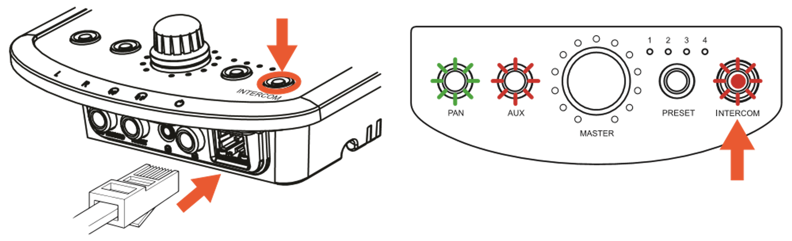
- Starting with power "off", press and hold the INTERCOM button while inserting the network cable to apply power.
- Continue pressing INTERCOM until buttons start flashing, then release.
- Toggle the intercom function by pressing INTERCOM button. LED "on" is intercom enabled; LED "off" is intercom disabled.
- To SAVE and EXIT, disconnect then reconnect power.
Signal Present Mode
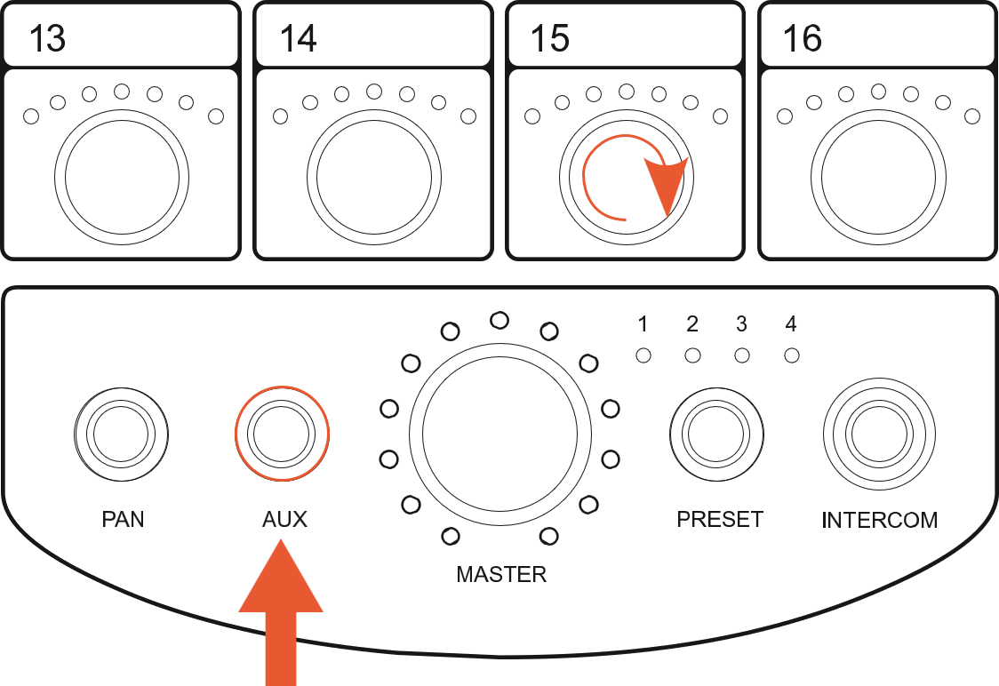
Press and hold the AUX button until it starts blinking (but less than 4 seconds) to easily see which channels have signal present without having to turn up each channel individually. If a signal is detected on a channel, the channel's LEDs will light up. Additionally, the MASTER knob's LEDs act as an overall RMS meter, showing you how much headroom is available. This makes it easy to see how close the Mixer is to clipping.
You are still able to adjust channel and master volume in this mode; however, the channel level indicator will only be shown briefly after making an adjustment, before returning to displaying input signal activity.
FW V5 and later enable the signal display function only when a preset has no submixes. It is also enabled in BANK mode.
- Press and hold AUX for 2 seconds until AUX button starts flashing.
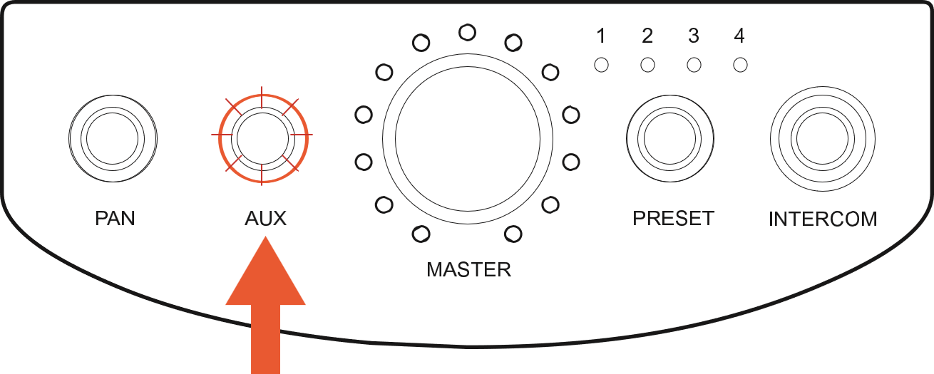
- LEDs above each channel blink to show audio signal is present.
- A level meter is displayed using LEDs around the MASTER knob to show the current RMS level of the mix bus.
- To EXIT, press AUX button.
Solo in Place
Solo-in-place allows you to listen to just one audio channel (all FW versions) or submix (FW V5 and later) without changing your current mix. Exit solo mode to return to your original mix.
- To enter press the AUX button and twist the desired channel's knob.
- The PAN and AUX buttons will flash to indicate you are in Solo Mode.
- Once in Solo-in-place mode, Solo other channels by twisting their knob.
- Solo levels are "solo-in-place", which means they are the same level as the mix (unless they are below 25%, then the solo levels are brought up to 25%).
- To adjust the solo level, use the MASTER knob.
- To EXIT Solo Mode, press ANY button (PAN, AUX, PRESET or INTERCOM).
Initialize Mixer (Zero Out)
For FW V2, zeroing out the Mixer will quickly reset all volume to 0%, unlink all stereo-linked channels, and move any panning back to center position.
For FW V5 and later, zeroing out the Mixer will set all volume levels to 0%, panning back to center, and one-to-one routing on all the channels (i.e. input 1 to knob 1, input 2 to knob 2, etc.). However links will remain in place as the linking function is stored in the Hub and is global over all Mixers.
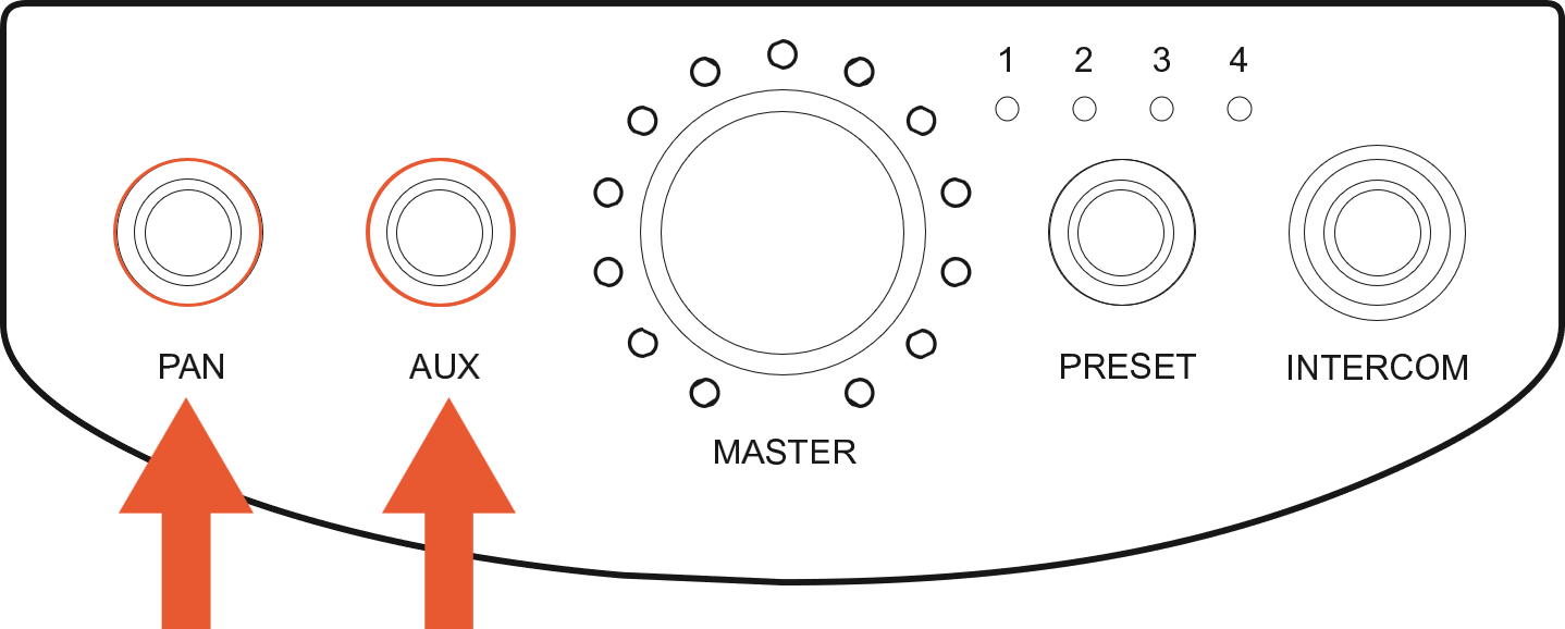
- Press PAN and AUX at same time for 2 seconds until all LEDs flash to reset all levels to defaults (all volumes to zero and PANs to center).
This will not wipe any existing preset settings.
Audio Limiter
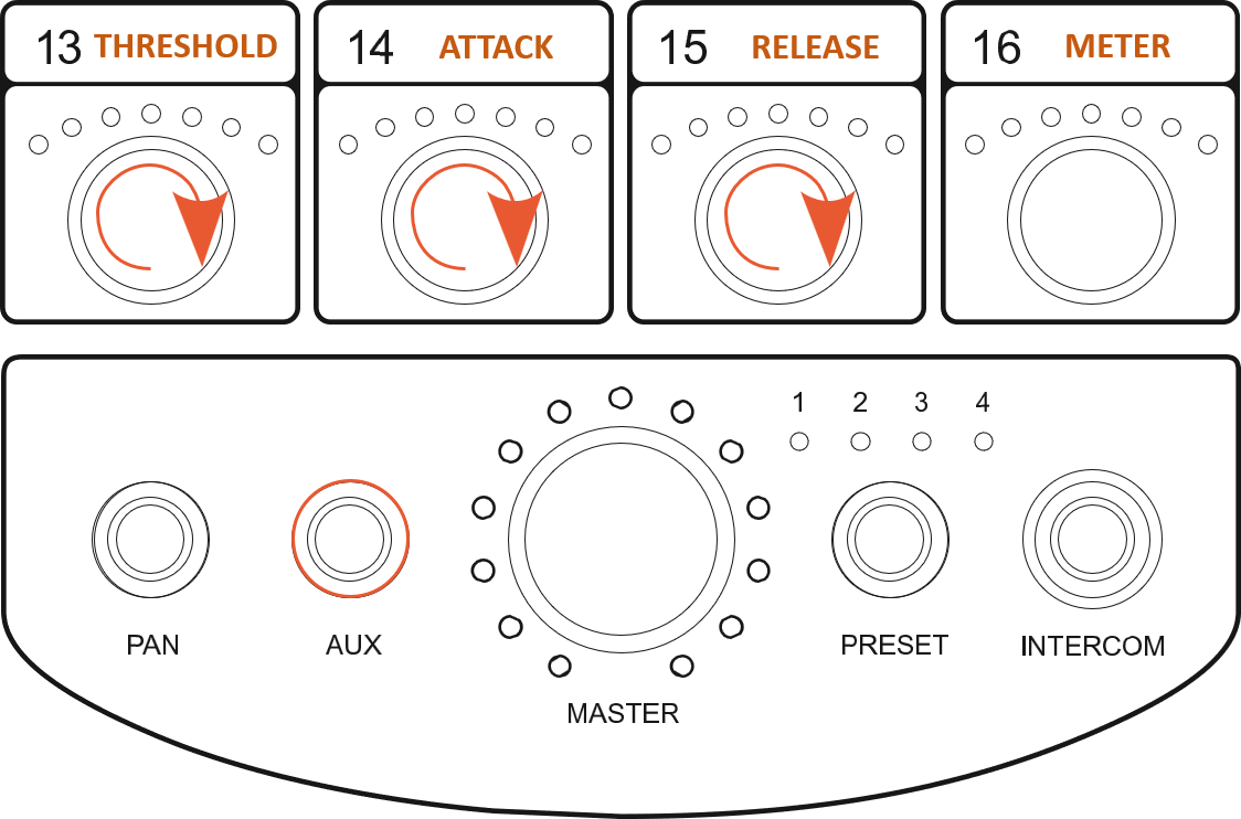
FW V6 and later offer the ability to set an audio level limiter. This will prevent audio from growing past a certain threshold given the following constraints. You enter the LIMITER settings page by holding the AUX button longer than 4 seconds. You can also set the LIMITER settings in the PRO Connect app.
THRESHOLD:
ADJUSTABLE: The audio threshold at which the limiter can engage to prevent further volume increase.
The AQUA LEDs on channel knob 13 (the bottom left channel knob) represent the threshold level.
ATTACK:
ADJUSTABLE: The amount of time it takes to begin limiting volumes once the threshold has been crossed.
The AQUA LEDs on channel knob 14 represent the attack time.
RELEASE:
ADJUSTABLE: The amount of time it takes to stop limiting volumes once limiting has engaged and the volume remains below the threshold.
The AQUA LEDs on channel knob 15 represent the release time.
METER:
This is a visual representation of the current level of limiting.
The AQUA LEDs on channel knob 16 (the bottom right channel knob) display the meter.
Mirroring
For FW V5 and later, two or more Mixers can be "mirrored" to reflect each other and operate in sync. The mirrored Mixers are "grouped" and you can have up to 16 groups, numbered 1-16. The Virtual Mixer Card when paired with a PRO Mixer uses group numbers higher than 16, thus leaving groups 1-16 available for mirroring.
The Mixers will emulate any changes or edits done to all in the GROUP, including pan and preset functions, with these default exceptions: AUX level, Intercom enable/disable, and Master knob level.
- To mirror a Mixer, press and hold AUX and PRESET, then twist the channel knob that corresponds to the GROUP you wish to join. (Example: Twisting channel 16 creates GROUP 16.) Repeat this on all Mixers you wish to join this GROUP.
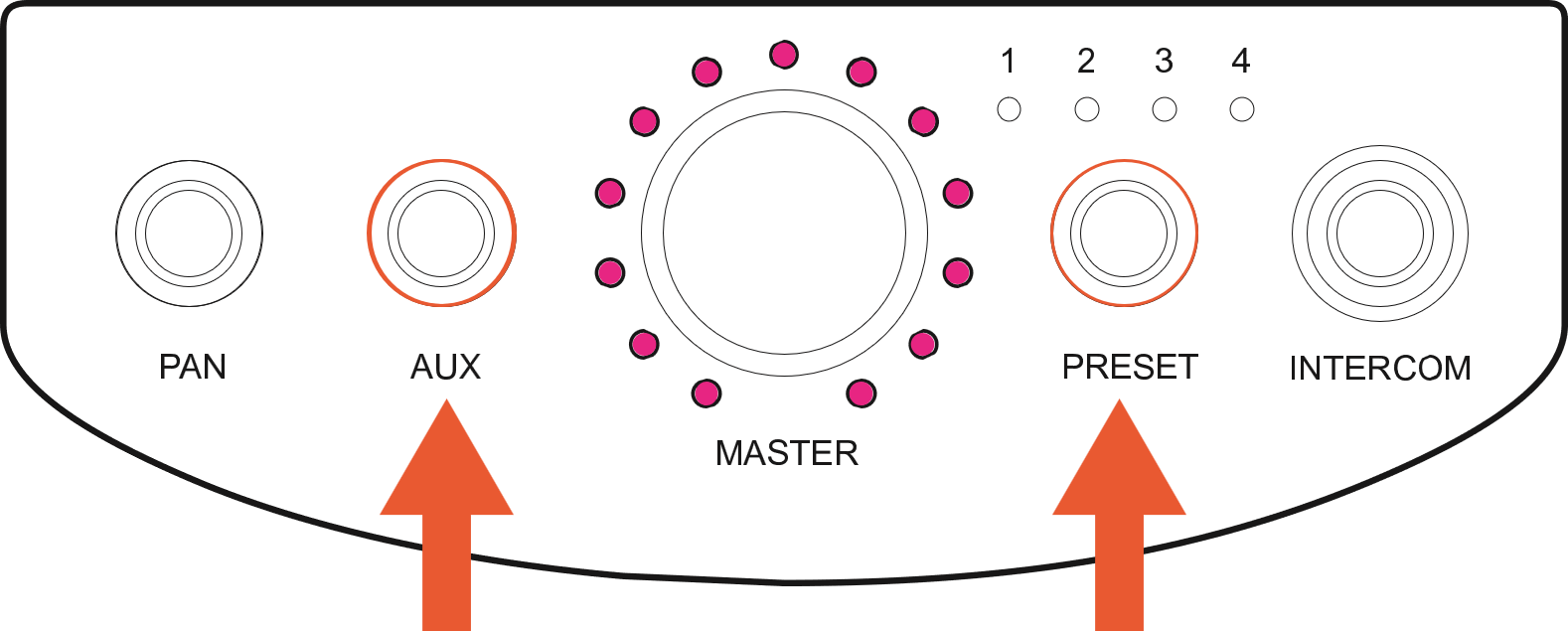
- When in a GROUP, the MASTER knob's BLUE LED's will dimly light up MAGENTA to indicate GROUP status. If using the PRO Digital Overlay, a box will outline the Mixer name in the main screen when mirroring is on and will display the group number.
- To DISPLAY the current group number of a Mixer, press AUX and PRESET at the same time.
- The LEDs will light up around the knob that corresponds to the group number.
- If the LEDs around the knob for channel #1 are lit, the group is #1. If the LEDs around the MASTER knob are lit, the group is #0, which means mirroring is turned off.
- To CHANGE group numbers, twist a channel knob while pressing AUX and PRESET buttons.
- To TURN OFF MIRRORING, press and hold AUX and PRESET and turn the MASTER knob.
Pairing with a Virtual Mixer
For FW V2 and later, a Virtual Mixer Card can be paired with a PRO Mixer allowing control of all the audio channels with presets and intercom.
The Virtual Mixer Card will not operate with the obsolete FW V1.
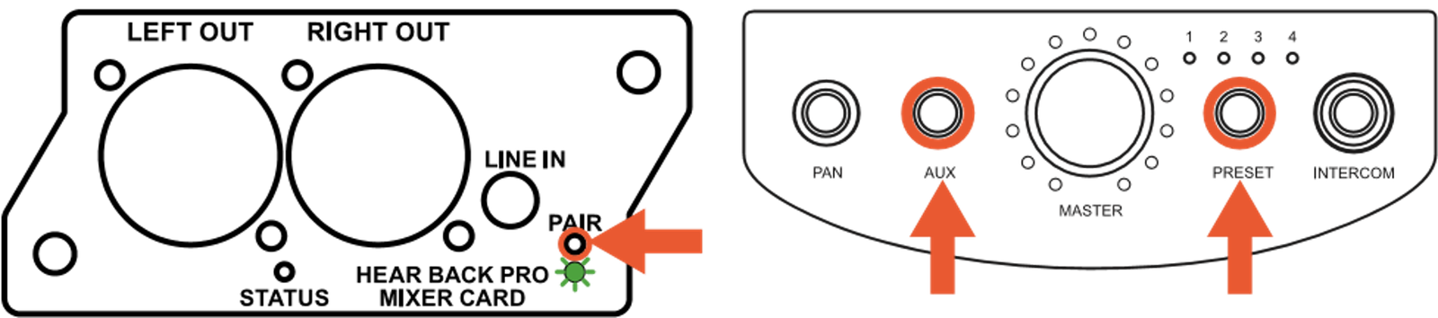
- On the Virtual Mixer card, hold the PAIR button until the LED begins blinking rapidly.
- After a few seconds, the LED will blink about once a second. Once this happens, press AUX and PRESET on the Hear Back PRO Mixer you wish to pair with the Virtual Mixer.
- All the LEDs will blink indicating that it is now paired.
- To UNPAIR, hold the AUX and PRESET buttons on the Mixer that is currently paired with the Virtual Mixer and then turn the MASTER knob. All the LEDs around the MASTER knob will light up, indicating the Mixer is NOT paired. After a few seconds, the LED on the Virtual Mixer card will not be lit.
Footswitch Operation
The PRO Intercom Footswitch silently mutes the microphone signal going to front of house, and routes audio only through the PRO Mixer intercom. The switch is momentary, simply let go and signal to FOH is restored. The footswitch utilizes a very low-level 22kHz signal that automatically engages the intercom feature on the Mixer (FW V2 bootloader 1.3 or higher). The footswitch eliminates the need for two microphones and simplifies use of the intercom.
Enable/Disable Footswitch
The easiest way to enable or disable the footswitch is to use the PRO Connect app.
The intercom must be enabled before you can enable the footswitch function.
To enable / disable the footswitch on the Mixer:
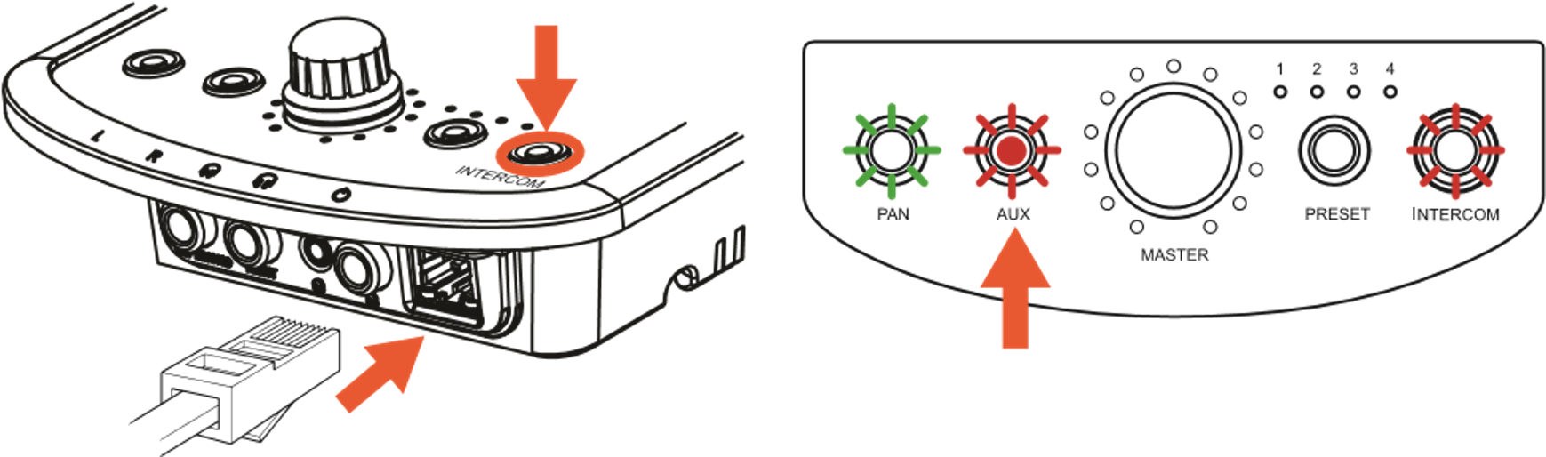
- Starting with power "off", press and hold INTERCOM button while inserting the network cable to apply power.
- Continue pressing INTERCOM until buttons start flashing, then release.
- Toggle the footswitch function by pressing the AUX button. LED "on" is footswitch enabled; LED "off" is footswitch disabled.
- To SAVE and EXIT, disconnect then reconnect power.
Mixer Bank Mode (128-Channel)
BANK Mode is intended for diagnostics and configuration. When you exit BANK Mode, your settings are lost. If you choose to keep your settings, don't exit BANK Mode. Submixing is not possible in BANK mode.
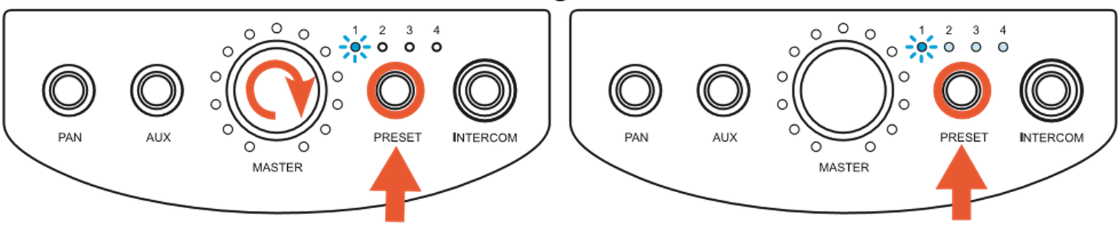
- Press and hold PRESET and spin the MASTER knob
- Selected preset LED will then flash ONCE per second and the other preset LEDs will light up dimly showing the other Hubs that are connected:
- 1 Hub connected: Presets 1 and 2 will illuminate (indicates BANK 1 and 2 are available)
- 2 Hubs connected: Presets 1-4 will illuminate (indicates BANKs 1 through 4 are available)
- 3 or 4 Hubs connected: Once you press PRESET to cycle through the BANKS (Presets 1-4), you will return to Preset 1 but will now be flashing TWICE per second, indicating you are in BANK 5. Continuing to press PRESET will advance you to BANK 6 (Preset 2), then BANK 7 (Preset 3) and then BANK 8 (Preset 4), with BANKs 5-8 LEDs flashing TWICE a second.
- You have access to all available channels in a one-to-one mapping.
- Step through the BANKs of channels (denoted by the Presets) by selecting a Preset (example: If Preset 1 and 2 are lit, then you have 32 channels to select from).
| PRESET LED | LED Flash Pattern | BANK | Channels |
|---|---|---|---|
| 1 | Single Flash | 1 | 1 - 16 |
| 2 | Single Flash | 2 | 17 - 32 |
| 3 | Single Flash | 3 | 32 - 48 |
| 4 | Single Flash | 4 | 49 - 64 |
| 1 | Double Flash | 5 | 65 - 80 |
| 2 | Double Flash | 6 | 81 - 96 |
| 3 | Double Flash | 7 | 97 - 112 |
| 4 | Double Flash | 8 | 113 - 128 |
Submix Edit Mode
Use this mode to choose what channels are going to a specific knob, such as a single mono channel, stereo pair, or a submix of up to 16 mono or stereo channels. A submix is when 2 or more channels are assigned to a single knob. You can assign up to 16 mono or stereo channels to a single knob. Accidentally going over that number will cause the Mixer LEDs to all flash simultaneously. You can also unroute a channel to turn off its LEDs.
You cannot submix an existing submix. It is not recommended to assign a specific input to multiple locations, especially multiple submixes.
- To enter Submix Edit Mode, press and hold PRESET then spin the channel knob that you're wanting to edit. LEDs will blink once. Release PRESET.
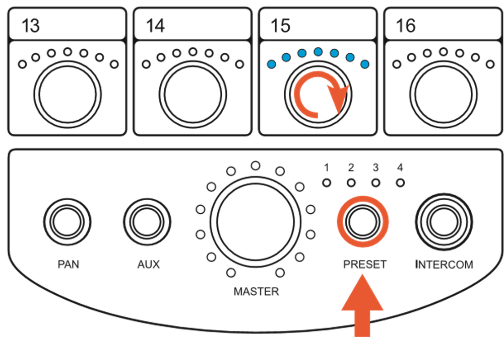
- You can select and edit channels (channels can be turned on or off). A channel with no LEDs ON indicates the channel is OFF or not assigned. A channel with all LEDs ON indicates it is the only channel (or stereo pair) assigned to the submix. If only one channel (or stereo pair) is assigned, then adjusting VOLUME, PAN, and WIDTH is disabled. If you turn up 2 or more knobs while editing, they will each display the respective levels. Adjust each level to balance the mix of channels. You can also adjust PAN and WIDTH (for stereo pairs only) if 2 or more channels are selected. Up to 16 channels can be assigned to a single knob.
- The Preset LEDs indicate the BANK of inputs currently selected (as described previously for BANK mode). Example: If Preset 1 LED is flashing (single flash) and Preset 2 LED is on, this would indicate that you are in BANK 1 of 2. If both Preset 3 and 4 were also ON, that would indicate you are in BANK 1 of 4.
- To save, press and hold PRESET for 2 seconds. All LEDs will flash, then the preset LEDs will go back to indicating only what preset the Mixer is presently on.
Edit Mode Examples of Use
There are countless combinations of routing, submixing and stereo linking. The examples below show simple combinations to gain familiarity with the "hardware" based procedure.
This example is based on a single hub system.
Assign a Stereo Knob
This example will sum channels 1-2 to the channel 1 knob.
- Ensure your selected channels are stereo linked (see STEREO LINK OPERATION).
- While HOLDING PRESET, twist the channel 2 knob, and release.
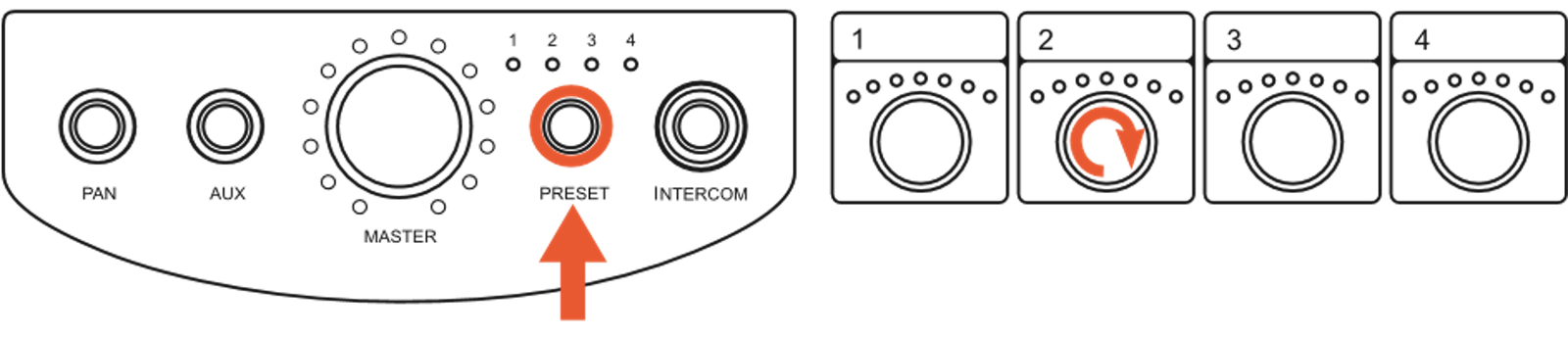
- Channel 1 LEDs will be lit solid and channel 2 LED's are flashing.
- Twist channel 2 knob. Both channel's LED's will turn off.
- Press and HOLD PRESET until the Mixer's channel LEDs flash quickly to indicate the setting is stored. You will notice that channel 2 LEDs are not lit. At this point, the stereo pair is present on channel 1 and channel 2 is now open for another assignment.
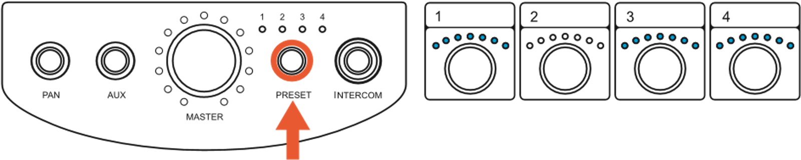
Create a Submix on a Single Knob
This example will create a submix on the now unused channel 2 knob.
- Hold PRESET, twist channel 2 knob, then release. All channel LEDs turn off. The Mixer enters EDIT mode.
- Twist the channel knobs you wish to be present in this submix. Remember you are setting the submix volume of that channel as you turn the individual knobs.
- Once you have everything set, press and hold PRESET until the LED flashes quickly to save the changes (see SAVE A PRESET).
- All the channels you selected are now present on the channel 2 knob. If you find one source is too loud or soft, simply repeat the above process, adjust, and exit.
Line Outputs
Two balanced 1/4 inch TRS line outputs are provided. The left operates as a mono output for sub woofers and mono devices if nothing is plugged into the right line output. When a 1/4 inch plug is inserted into the right output, the line outputs operate in a normal stereo mode. The line outputs may be used simultaneously with the headphone outputs, and are both controlled with the master volume knob. In the event of ground loops when connecting the Mixer line outputs to other devices that have an earth ground, it may become necessary to lift the shield at the Mixer outputs.
NEVER lift or disconnect the AC safety ground on the AC power supply cable of any device.
Headphone Amplifier
The headphone amplifier outputs are paralleled outputs. When using multiple headsets, the total impedance should not go below 16 ohms. The headphone amplifiers are very powerful and can easily damage in-ear transducers, headphones, and your hearing; exercise great care in adjusting the master volume. At 32 ohms, the amplifier is capable of sustaining 2 watts of power per ear! The amplifiers are short circuit protected, and will cause the status indicator logo to blink RED if overheated.
Mixer Name
The Mixer name can be updated via the PRO Connect software. More information can be found here: Digital Overlay
Firmware Version
It is recommended to check and update the firmware version of all PRO equipment using the PRO Connect Software.

New interface. New level of control.
PRO Connect provides a web-based interface to update, configure, and control your Hear Back PRO and Switch Back PLUS systems.
 [Download for Windows]
 [Download for macOS]
To check the version on the Mixer directly:
- Starting with power "off", press and hold PRESET button while inserting network cable to apply power (until buttons flash).
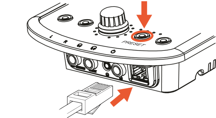
- The LED that is lit around the MASTER knob shows the major firmware version. The channel knob lit with BLUE LEDs indicates the minor firmware version 1-16. With lit GREEN LEDs, the minor firmware version is channel number + 16 = 17-32.
- Example: If the first LED is lit around the MASTER knob and the LEDs above the channel 7 knob are lit BLUE, the firmware version is 1.7.
- To display the bootloader version number, press the PAN button. The version number is display in the same way.
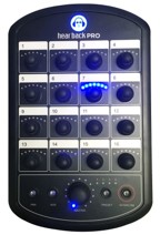
- To EXIT, disconnect then reconnect power.